
Productsproducts
Contactcontact
- Contact:
- Tel:+8613868770229
- Phone:+8613868770229
- Mail:jiangku@cnjkdq.cn
Searchsearch
Newsnews
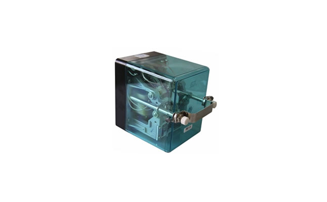
JRJC1-70/240 Plug-in AC Binary Relay
- Product Details
Product Usage
JRJC1-70/240 plug-in AC binary relay is used at the receiving end of the 25Hz phase sensitive track circuit in the AC electrified section station, which can reliably reflect the occupancy and clearance of the track circuit.
Applicable environment
1. Atmospheric pressure: not less than 70kPa (no more than 3000m above sea level)
2. Ambient air temperature: -40℃~+60℃
3. The relative humidity of the air: not more than 90% (temperature +25℃)
4. Vibration frequency: frequency is not more than 15Hz, acceleration amplitude is 4m/s2 (0.4g)
5. Working position: horizontal
6. There should be no harmful gas causing explosion hazard around, and preventive measures should be taken.
Executive standard
When the wing plate is in any position, the gap between the wing plate and the pole face of the iron core is not less than 0.35mm.
The contact pressure, contact gap, and bracket gap of the relay should meet the requirements of Table 1.

The contact resistance of the relay contact should meet the requirements of Table 2 (unit: Ω)

Number of relay contact groups: 2Q, 2H
Relay identification pin number: 11, 22
The electrical characteristics of the relay (at +20℃) should meet the requirements of Table 3

Table 4 Relay coil resistance

Applicable environment
When the ambient temperature is +20℃, the coil resistance of the relay should meet the requirements of Table 4. Under other environmental conditions, the direct current of the coil should be converted according to the following formula.
R1=R20[1+a(t-20)]
Where:
R20--Resistance value at +20℃, Ω
Rt-The resistance at an ambient temperature, Ω
t—Ambient temperature during measurement, ℃
a--The temperature coefficient of resistance of the conductor material of the tested coil (copper is 0.0041/℃)
The relay magnetic circuit should be balanced. When the local coil is applied with a voltage of 50Hz and 220V, the induced voltage of the track coil should not be greater than 5V after the 5uF capacitor is connected.
The relay coil is energized according to Table 3, the contacts are connected to a DC 24V, 1A non-inductive load, and the electrical life of the relay is 200,000 times.
Under the standard atmospheric conditions of the test, the despair resistance of the relay should not be less than 100MΩ.
Under the condition that the air pressure is not lower than 86kPa (equivalent to the altitude below 1000), the insulation withstand voltage of the relay should be able to withstand AC sine wave 50Hz, 2000V rms voltage, and there should be no breakdown flashover after 1Min. The voltage should be 75% of the original test voltage value.
test method
Temperature: 15℃~35℃
Relative humidity: 45%~75%
Air pressure: 86kPa~106kPa
Requirements for testing measuring tools, meters, and power supply
The accuracy of the measuring gauge should not be less than 0.02mm
The accuracy of the DC voltmeter used for testing should not be less than 0.5
The accuracy of the AC (25Hz) voltmeter and AC ammeter used for testing should not be lower than level 1
When testing electrical characteristics, the distortion of the output waveform of the 25Hz test power supply should not be greater than 5%. The power supply voltage fluctuation range should not exceed 5%.
The relay test procedures and methods shall comply with the relevant requirements of the national standard GB/T 6902-2001 "Experimental Methods of Railway Signal Relays".
Dimensions
The appearance and installation dimensions of the relay socket are shown in Figure 1.

Installation Precautions
1. The user manual must be authenticated and read before using the relay.
2. The number of the relay contact system is shown in Figure 2. When in use, the socket must be installed with an identification pin as specified in the user manual.
3. The use environment of the relay should have good ventilation conditions and dust-proof equipment. It is applicable in specially designed circuits; when used in special circumstances, the electrical characteristics and contact capacity of the relay should be considered to ensure reliable operation of the relay.

Faults and troubleshooting methods
Problems that should be paid attention to when adjusting and overhauling binary relays
1. If the wing plate itself is found to be uneven, loosen the bearing nut, unscrew the bearing screw, carefully remove the wing plate and place it on the platform and level it gently. When installing, carefully adjust the left and right positions of the bearing screws to keep the wing plate in the middle of the gap between the two levels of the iron core. When the wing plate is rotated to any position, the distance from any pole surface is not less than 0.35ma, and then tighten the bearing. Nut. Keep in the original position when tightening, so that the wings and contacts can move flexibly and freely.
2. If the cotter pin is found to be invalid and the nuts of each part are loose, adjust the cotter pin and tighten it again. Keep in the original position when tightening, so that the wings and contacts can move flexibly and freely.
3. In the released state, the setting plate or stop should be in contact with the lower stop wheel. Keep this state by hand, check the mechanical characteristics of the binary relay, and use an adjustment tool to make it meet the mechanical characteristics requirements.
In working (pull-in) state. The wing plate or the stop should be in full contact with the upper stop wheel. At this time, according to the provisions of 2.1 (when the wing plate is in any position, the gap between the wing plate and the pole surface of the iron core is not less than 0.35mm.
4. Check the mechanical characteristics of the binary relay, and use the adjustment tool to make it meet the requirements of Table 1.
Analysis and Treatment of Common Electrical Faults of Binary Relay
a. Failure phenomenon: large working value.
cause of issue:
1. The fit between the bearing and the shaft is tight. The axial clearance is small.
2. The wing plate has foreign matter jamming or pole surface friction in the magnetic pole gap.
3. The neutral of the wing plate is too large, and the weight nut is loose or too close to the shaft.
4. The front contact pressure is too large.
Treatment method: adjust the weight nut to the shaft to increase the gravity of the plate, but it should be ensured that there is enough margin for the working value.
b. Fault phenomenon: the release value is small.
The cause of the failure: the gravity is too small.
Solution: Adjust the weight nut to the shaft to increase the weight of the wing plate, but it should be ensured that there is enough margin for the working value.
The cause of the failure: the front contact pressure is too small.
Treatment method: appropriately increase the front contact pressure.
C. Failure phenomenon: The ideal phase angle cannot be measured.
1. The cause of the failure: The rail transit voltage is not applied as required by the electrical characteristics test of the relay, and the phase angle cannot be measured.
Failure performance: This failure performance is that the indicator light of the test bench is always off during debugging.
Treatment method: As long as the family rail voltage can be tested.
2. The cause of the failure: the primary coil of the B2 transformer in the electrical characteristic test circuit is connected reversely.
Fault performance: This fault performance is that only one angle can be measured.
Treatment method: change the primary coil of the B2 transformer and connect it.
Comments Box